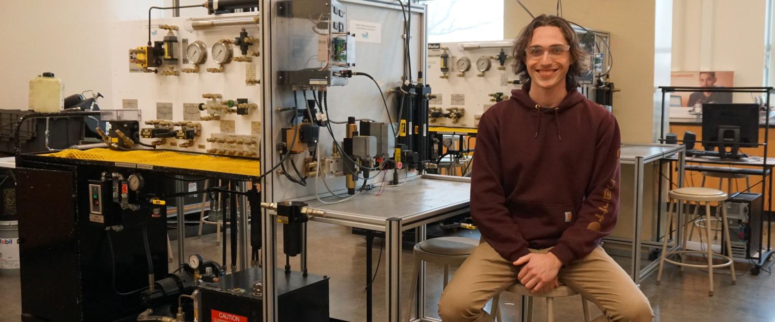
Student in Parker classroom

Motion and Control Laboratory

Supported through ongoing grants from Parker-Hannifin Corporation since 2003.

Th Parker-Hannifin Motion and Control Laboratory at Â鶹´«Ã½ trains undergraduate and graduate engineers in hydraulic, pneumatic and electromechanical systems engineering.  The lab is focused on hydraulic system engineering experiences and  Â鶹´«Ã½ exposure to pneumatic and electromechanical systems.

Hydraulic trainers

desk

The two Hydraulic Trainers offer the ability to construct hydraulic circuits using the mounted elements, quick-connect hoses, and installed pump.  The maximum flow and pressure produced are 2.7 GPM and 500 psi, respectively.  Available hydraulic circuit elements include:

  • 5 GPM analog flow meter
  • 1000 psi analog pressure gauge (2)
  • One-way flow valve (2)
  • Variable flow control (needle) valve
  • Pressure compensated variable flow control value
  • One-way variable flow control valve (2)
  • Manually operated, closed-center, 4-way directional control valve
  • Solenoid operated, open-center, 4-way directional control valve
  • Double-acting, single-rod piston actuator, 6 inch stroke
  • Double-acting, single-rod piston actuator, 12 inch stroke
  • Piston accumulator with gas precharge pressure gauge
  • Sequence valve
  • Pressure control valve
  • Deceleration valve
  • Fixed-displacement hydraulic pump/motor

Electro-Hydraulic Trainers

photo of electrohydraulic trainer

Two electro-hydraulic trainers combine digital data acquisition and control with electro-hydraulic elements. These stands offer experiments in the adjustment of electronically controlled values, system identification and control methods. The stands incorporate a BD101 signal conditioning card that functions as a servo valve driver with the option for input bias and scaling and a closed-loop proportional-integral controller. The card is normally connected to a PC via National Instruments hardware. The stand includes the following electro-hydraulic elements:

  • D1FX proportional 4-way directional control electronic valve
  • D1FH high frequency, two-stage pilot operated, 4-way directional control electronic valve
  • DY3H high frequency, two-stage, 4-way directional control electronic valve
  • BD15 high resolution, flow control electronic valve
  • Double-acting, single-rod piston actuator, 12 inch stroke, with LVDT position sensor

Computer work station

photo of computer work station

Each electro-hydraulic trainer stand is connected to a workstation with a PC. The connection to the stand is via a National Instruments SCB-68 breakout box attached to a National Instruments PCI-6251 data acquisition card that resides inside the PC. The PCI-6251 has the capability of reading 16 singled-ended or eight differential analog inputs with 16 bit resolution at up to 1 MHz; the ability to produce two analog outputs with 16 bit resolution at up to 2.68 MHz; two 32 bit counters/timers; and 24 digital inputs/outputs.  The data from the Electro-Hydraulic trainer stand is available to both MATLAB and LabVIEW environments for data collection and/or control.

three Â鶹´«Ã½s perform with the hydraulic trainer

Labs that Â鶹´«Ã½s perform with the hydraulic trainer include measuring flows and pressures associated with different hydraulic circuit elements and developing algebraic models of hydraulic elements. Labs that Â鶹´«Ã½s perform with the electro-hydraulic trainer (right) include working with servo valve electronics, dynamic system identification and closed-loop control. 

For more information

Dr. Rick Meyer, Associate Professor of Mechanical and Aerospace Engineering, College of Engineering and Applied Sciences at Â鶹´«Ã½ (269) 276-3427